For component values, refer to the article in the PDF link above

These two little homebrew transmitters caught my eye at a ham swap meet. I like simple homebrew circuits and was intrigued by the size and the fact that these transmitters used just a single tube and yet were MOPA circuits (master oscillator - power amplifier). I had always assumed that the 6SN7 was a good dual triode audio preamp or TV oscillator tube but not something suitable for a transmitter. In doing some research, I found a 6SN7 transmitter (and a matching receiver) in the August 1952 QST magazine (link is to PDF file hosted by W4JKL). Both of the little transmitters are similar in design to the one in the QST article although the age of the components inside indicate more recent construction.
Schematic and differences
The transmitter with the meter is the older of the two. Its circuit is parallel feed to the final plate using an RF choke and a fixed cap to keep the B+ voltage off the exposed final tuning cap on top of the chassis.

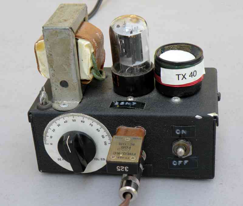
Both of the little transmitters include a NE-2 neon bulb to show relative RF voltage. The metered set also uses a NE-2 as pilot light.

Repairs
With a piece of homebrew gear, the question always arises as to whether it was properly built in the first place. Did the constructor take shortcuts? Did it actually work properly?
I inspected the innards of both transmitters. The smaller black wrinkle set appeared rather crowded underneath, in part because the tuning cap takes up a fair amount of space. I checked for wires and connections that might be too close to each other and added a bit of electrical tape in several places. The older metered set was obviously less crowded. Except for the crowding on the black-wrinkle unit, both transmitters were rather well constructed and worked when properly matched coils were installed.
Coils
The coils that were sold with the transmitters were nicely constructed from old 4 pin tube bases. However, the coils had apparently been made for a different purpose since the plug connections did not match those of the 6SN7 transmitters. I modified the pin-outs of the coils to match the transmitters.

Homebrewing a Coil with Recycled Material
I also decided to make a coil or two out of found materials. The coil forms of yester-year are not readily available.
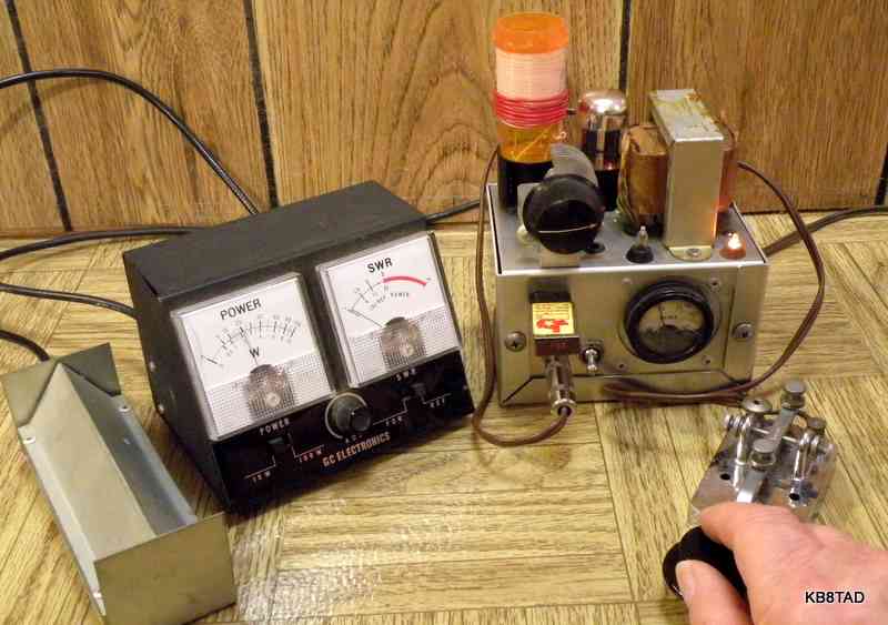
For wire, I ripped open a length of scrap CAT-5 ethernet cable and pulled out and straightened the solid wire inside that looked to be 22 gauge. I had previously tested a plastic pill bottle for heating in a microwave oven to see if it was RF transparent. It did not heat up and would likely work fine as a coil form. I drilled several holes in it. A couple of strips of double-stick carpet tape worked fine at holding the wire in place as I wound the coil for most of the length of the pill bottle. I then plugged that temporary single tuning coil into the un-powered transmitter with a couple of banana plugs and used my grid-dip oscillator to determine the range achievable with the transmitter's 100 pF tuning cap. The initial range was about 2.2 to 4.5 MHz. I removed some of the coil turns which provided a new range of 2.5 to 5 MHz allowing the 3.5 MHz point to be at about the half-mesh position for the cap. I then wound a separate 6 turn coil next to the bottom of the tuning coil for the output link to the antenna and ground. Testing the 80 meter coil with a 50 ohm dummy load provided an output of about 1.5 watts, slightly less than with another coil that I had tested. Thinking that those 6 turns may have been one or two turns too many, I experimented further using some solid 20 gauge hookup wire wrapped over top of the lower turns of the tuning coil. I temporarily clipped that hookup wire directly to the output coax. I added one turn at a time starting with 3 turns. The output increased with each turn until I again had 6 full turns but this time my wattmeter indicated a full 2 watts output.
Overall design
I was frankly surprised that these little transmitters would do over 1.5 watts on 40 meters and 2 watts on 80. They are fun pieces for showing what minimalist one tube sets can do. Lots of hams prefer QRP at these low powers. With a good antenna, such a rig is all that is needed for far-reaching contacts. The link coupling might be a weakness, but a simple antenna tuner can be added for full control of loading and harmonic suppression.
Check out Andy's (UU1CC) 6SN7 transmitter for real artistry in homebrew, wood-work and photography.
10-14-10
The Homebrew Galena Crystal Set was the previous item on the bench.