

This home-brew amp with two 813 tubes for the final was made by an unknown amateur radio operator (ham) some years ago. I am assuming it to be about 35 to 40 years old. I originally bought the piece at auction because of the rack-mount cabinet in which it was installed but became intrigued by what seems to be a relatively simple circuit, a parallel wired pair of 813 tubes in a grounded-grid configuration. I did not have a high voltage power supply for it so had to build one (more info on power supply below). The piece has a filament transformer mounted under the chassis. As can be seen, the 813 tubes glow quite brightly with the filaments powered (10 volts at 10 amps).
Caution
I have limited experience with transmitters and RF amplifiers so tend to err on the side of caution. Also, lethal high voltage (Over 2500 volts DC) is present on top of the chassis as well as under when a high voltage power supply is connected.Due care and caution are warranted. An understanding of the circuit is a must. I have not yet found the exact circuit in any of the ham radio magazines. Editors and Engineers' RADIO HANDBOOK, 17th edition, by Bill Orr comes the closest with a grounded grid circuit that allows for various final tubes including a pair of 813 types. The power input was designed to be about a kilowatt.
Initial checks and tests
I cleaned the unit and found several bad solder joints on the bandswitch, its coil, and on one of the filament connections. Apparently the heavy copper wires needed a hotter soldering iron than was available. The variable cap pre-loading had been loosened to the point that the caps scarcely held their settings. I adjusted the preloading. The AC power chassis connector was a FEMALE connector requiring a plug-to-plug AC cord, a dangerous situation. Since the unit is homebrew, I modified the opening and mounted a computer-style 3 wire male chassis connector. On powering the unit with filament voltage (shown), I measured 10.0 volts at the tube pins, the correct voltage. The current meter responded to a low DC voltage test, but it proved to have a sticky meter pointer. I will repair or replace it. The filament choke is a nice homebrew bi-filar winding on a ferrite rod. The exciter input circuit is untuned, just a 0.001 mike cap to the cathode.
Design of a power supply
I inquired about using an electrically matched pair of junk microwave oven transformers (secondary is about 2100 volts AC) and rectifiers for a high voltage power supply. Opinion is divided on whether this idea will work. The transformers have one side of the secondary connected to the frame. The use of a pair will allow for a full-wave power supply while keeping those connections on the frame at or near ground potential.
Here is a PDF file of an article in QEX that describes such a supply.
I located a set of ten 500 MF electrolytics at a voltage rating of 310 each. I reformed each one separately. These came with 10K ohm ten watt equalizing resistors.
If you recognize this amp or if you have experience with similar homebrew amps and/or use of microwave oven transformer power supplies, let me know.
Here is an Australian ham club's homebrew kilowatt amp using a pair of 813 tubes and a pair of microwave transformers in the power supply.
Here is a link to WB8ERJ 's linear amp project using a pair of 813 tubes. The amp is under construction.
More progress reports Pictures of the finished power supply I built are below. The magnetic shunts were removed from the microwave oven transformers as per the instructions in the articles noted above. I used very low voltage for testing and to determine the proper phasing of the transformers. The original 3 volt magnetron filament winding was connected in series with the primary to reduce the high voltage a bit. I re-used the two high voltage diodes. Microwave oven diodes are typically rated at around a half ampere at well over twice the PIV needed in this circuit.
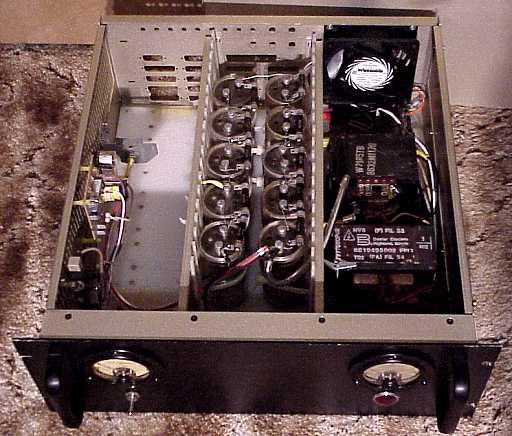
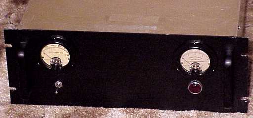
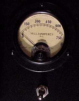
Rather than measuring the entire high voltage DC for the high voltage meter, I used a portion of the bleeder chain to feed the meter. That keeps high voltage stress on the series meter resistors to a minimum. To measure current draw, I lifted the grounded end of the high voltage secondary on each transformer and inserted a milliammeter and its shunt between those points and chassis ground.
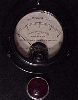
The initial current to a capacitor chain is quite high since the supply sees an initial near-short-circuit until the caps are partly charged. I used a variac for early testing to bring the voltage up slowly to avoid stressing the diodes. In looking for a soft start circuit, I noticed that the tiny microwave oven control relay from the left-over parts had a current rating of 16 amperes at 250 VAC. The microwave oven circuit board containing the relay also had a small transformer, diodes, and cap that supplied a bit of power to activate the relay coil. I removed the excess circuitry including the discrete transistors controlling the relay, bypassed the relay's transistor control connection and tested the board. Using a variac, I determined that the relay closed when about 60 volts was supplied to the board. That could be extended upwards by adding a resistor in series with the relay board's AC input. The little circuit board was perfect for soft start of the power supply. I used a 25 watt 25 ohm and a 15 watt 12 ohm resistor in series to limit the turn-on surge. The relay closes to bypass these power resistors after the transformer primaries climb above 60 volts or other selected point. The soft-start worked perfectly. Power supply output is 2550 volts with the draw of the bleeder resistors.
The voltages in this power supply and in microwave circuits are lethal. Caps retain charges. If you are not experienced with building and using high voltages sources, or do not fully understand the circuits and risks, do not build or experiment with a supply of this type.
A Heathkit DX-100 was the previous item on the bench.