
BC-348Q receiver with Hallicrafters-made Navy power supply
I have worked on several BC-348 receivers over the years. Here is another one. This is serial number 2896 and is another "Q" version made by Wells Gardner. Designed for the Signal Corps, the BC-348 is a World War II receiver for the U.S. Army Air Corps. The BC-348 was used as the long-distance liaison receiver for large aircraft such as the B-17 and other bombers in World War II and into the early 1950's. It features 6 bands with one for long wave from 200 to 500 KHz and five for shortwave from 1.5 to 18.5 MHz. Only a small part of the upper end of the AM broadcast band is covered.
Here is a link to another BC-348Q I repaired a couple of years ago with lots more information and here is a link to my first BC-348 back when smaller pictures were the norm on the net.
The appeal of this set
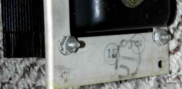
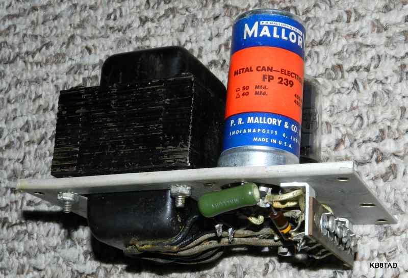
I purchased this set at a hamfest. It appealed to me not only because the price was reasonable, but it had no front panel modifications, no extra holes in the cabinet, and included the shock-mount. As expected, it had been converted to use an AC power supply in place of the original dynamotor. The typical AC supply for the BC-348 is homebrew with wide variation in quality. However, this set had a surprise inside, a factory-made EP-298 conversion AC power supply built by Hallicrafters for the Navy as evidenced by the Navy acceptance stamp on the bottom of the power supply chassis. Note that a few sets have been found with a Navy plate indicating conversion to 60 cycles 115 volts. This set did not have such as plate. I assume the Navy used the converted sets to monitor large bombers and even the early Presidential planes which had this type of liaison radio equipment on board. Let me know if you have detailed information on how the Navy used converted BC-348 receivers.


Repairs
Zero bias - This BC-348Q was working but with weak and distorted reception and some hum. A quick check of the voltage from the electrolytic shell to the output transformer B+ connection showed only about 150 volts instead of the expected 240 volts ballpark. The B- in a BC-348 is actually at about 16 to 18 volts negative with respect to the chassis. This provides a source of bias for the 6K6 audio output tube. The power supply filter choke is in that negative return lead and has that same voltage on it, a clever way to keep high voltage off the choke but still provide choke-input filtering.
A quick check for voltage between the electrolytic shell and the chassis confirmed the presence of that negative voltage. Therefore I assumed that the expected bias for the output tube was present. However, I noticed that the 6K6 was running hotter than I would have expected, possibly pulling more current. Could that the reason for the low B+? I pulled the inspection cover from the front panel and checked for the presence of bias on the 6K6 input grid. The input grid was at zero bias. Thinking that a leaky capacitor might be responsible. I started checking the input capacitor and also the resistors in the bias circuitry. At that point I found what looked to be an open resistor in the bias feed. Probing the resistor a bit proved that it was moving easily. It was not open, just not soldered on one side! I had found a nearly 70 year old factory defect! My guess is that the set performed fine early in its life with simply the mechanical connection but that the connection opened up later.
Bad electrolytic - Soldering the resistor restored proper bias to the tube but B+ increased only to about 170 volts, still not adequate. Finding proper voltages at the plate connections of the 5Y3 socket, the next suspect was the power supply electrolytic itself. I pulled the power supply and carefully removed the electrolytic from the phenolic insulator mount. Testing it showed the right capacitance but my Sencore LC-75 capacitor analyzer flashed all eights on the ESR test as if to say, "are you kidding?". I found a new old stock Mallory in the junque box that reformed quickly at full voltage and easily passed the ESR test. The original cap was 40 MFD and 10 MFD using 40 as the input side of a pi filter. The Mallory replacement was 40 and 50 MFD. The 40 MFD was used for input side to match the original to avoid stressing the 5Y3 rectifier. The secondary side can be higher than 10 MFD with no problems.
Replacing resistors - While replacing the electrolytic, I noticed that the 5 watt 500 ohm power supply resistor in the pi filter had been replaced with a couple of half-watt 47 ohm resistors probably to try to boost the low B+. I replaced that pair with the correct resistor as well as the 100K ohm bleeder which was open. After replacing the rebuilt power supply, B+ voltages were normal and the sensitivity of the radio was very good on a couple of the bands.
Audio distortion - However, the audio was still somewhat distorted and not as loud as I would have expected. Was the 6K6 damaged by improper bias? I tested the 6K6 and all the other tubes with my military TV-7 tube tester. The readings on that tester are normally a bit on the stingy side. However, all the tubes tested as new. What could be causing the low and distorted audio? Then it dawned on me. I was using a proper audio transformer on my speaker to match the 4000 ohm impedance typical of the BC-348. However, the output transformer tap had been changed to the "Low" side, 300 ohms impedance. I had stupidly overlooked the obvious! Connecting the tap back to the high 4000 ohms setting solved the audio problems.
Cleaning controls - A good cleaning of the volume and RF gain controls eliminated the noise in those controls. Deoxit on the bandswitch contacts also solved an intermittent loss of signal that could be fixed by bumping the bandswitch knob.
Alignment - I followed up with adjusting the BFO control and an alignment. The alignment trimmers needed to be loosened with a large screwdriver before I could use my normal alignment tools. A couple of the bands were quite close to the proper settings and showed very good sensitivity but alignment improved the others significantly. The VLF band was originally the worst for sensitivity. After alignment, all of the bands showed excellent sensitivity. The VLF band was originally only able to hear the local airport beacon. After alignment, I heard a number of beacons.
Modifications
The set now has a proper 3 wire power cord. I used a couple of insulated push-on connectors for tightly attaching to the blades of the rear power connector that Hallicrafters had selected for power input and used a solder lug under a nearby chassis screw for the green safety ground. To minimize modifications, I did not re-purpose the original fuse holder but instead replaced one of the wires to the power switch with a wired inline fuse holder.
Solid state rectifier - Since the original power supply was a dynamotor, B+ would have been available almost immediately. I decide to try replacing the 5Y3GT in the Hallicrafters power supply in an easily reversible fashion. I soldered two 1N4007 diodes into a tube base adding a 500 ohm 5 watt resistor to make up for the increased efficiency of the diodes. The combination worked very well. I measured 240 volts B+ as the result, about 5 volts less than shown in the Hallicrafters power supply schematic but closer to the original design specification for the BC-348 at 228 volts.

Those other capacitors - My previous experiences with the metal-sealed caps in the BC-348Q showed that they are not likely to be leaky. That was also true in this set. The metal-sealed caps in this set were still good despite the years.
Low audio? The surplus conversion manuals suggest adding a triode tube stage to increase the audio level of this set. I have not found that to be necessary. However, if more audio gain is needed, I suggest using a modern powered speaker. That works very well if the audio output is changed to the "LO" 300 ohm tap. I tested a couple of cheap computer powered speakers. I used a temporary clip lead directly to the 300 ohm "LO" tap and chassis ground as input to the powered speaker. No matching transformer was needed. If no other connection is made to the headphone jacks, then I suggest adding a 300 ohm resistor in parallel with the input to the powered speaker to provide a constant load on the BC-348 output transformer.

One source on the net suggested leaving one headphone jack at the 4000 ohm "HI" connection and wiring the other to the "LO" 300 ohm connection. That is a good idea and is an easily reversible modification. I opted to leave this example as close to stock as possible and did not do that.
Performance
I've seldom been disappointed by a properly working BC-348, but this set was definitely one of the best. This set was also as close to stock as any I have ever worked on. The crystal filter and BFO did an excellent job when tuning in SSB on the 80, 40 and 20 meter ham bands. The set was very stable. I wished I had had one of these radios in my early shortwave listening days.
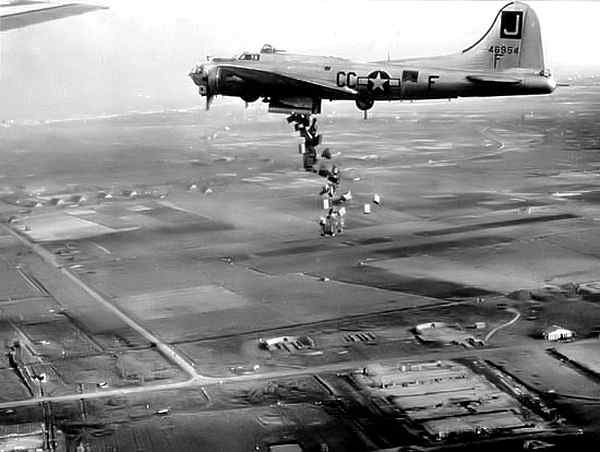
Standard equipment on the B-17
All B-17 "Flying Fortress" bombers carried a BC-348 as part of long-range radio equipment. Here are a couple of Army Air Corps photos of the aircraft.

More information
More information on the BC-348 can be found at this link to a BC-348Q I repaired a couple of years ago.
Hallicrafters produced one other item with an "EP" prefix, the EP-132, a 19 tube VHF-UHF receiver for the Navy. Its power source was also 120 Volts AC.
The manual for the BC-348J,N,Q version can be easily located on the web. BAMA has a copy but a higher resolution PDF copy can be downloaded from James Moorer's excellent website.
Information on possible ham modifications that might have been applied to a BC-348 can be found in Volume 1 of the Surplus Conversion Manuals available from W7EKB's glowbug site.
Click for a list of links to these and other military manuals.
List of other US military radios I have repaired.
Here is an
index to my other US military radio projects.
Date 2-25-13
A Heathkit MR-18 Marine direction finder radio was the previous item on the bench.