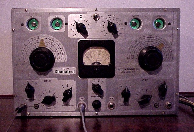
Rider Chanalyst after cleaning and repair
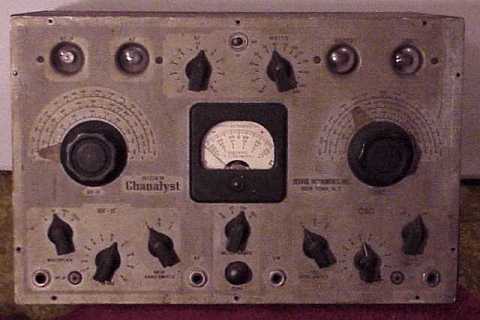
another Rider Chanalyst model 11
See the previous Rider Chanalyst 11 I restored for lots of information on what this piece is capable of doing. This neat piece of test gear has four 6E5 eye tubes.
See also the Meissner Analyst that is almost a pure copy of the Rider Chanalyst.
My thanks to Bruce M. for giving this piece a good home. The following picture shows the Chanalyst before cleaning. I used white waterless hand cleaner and lots of old soft toothbrushes to scrub its face, the chassis and the individual knobs. You can see the difference in the front panel before and after.
Repair progress
After cleaning, I checked for leakage in several of the screen grid and cathode bypass capacitors that already had one end cut loose. Replaced several of the smaller caps with ceramic equivalents. Did several safety checks. Soldered a bad rivet on the fuse holder, cleaned the on-off switch with deoxit. Replaced the missing line cord. Pulled the 6X5 rectifier tube. Then proceeded to check the power transformer for just the filament heating load.
Using my isolated variac, saw the current draw go up very quickly and exceed the normal full load of about half an amp with the variac at only about 30 volts. Unplugged and looked for a possible short circuit in the filament line or elsewhere. Unsoldered the filament leads and then all other secondary leads. Same problem. Conclusion is bad transformer. Most likely a shorted section in the high voltage winding.
Update, replaced transformer and electrolyticHad a couple of potential candidates (yes, bad pun) for a replacement power transformer in the "boxe de junque". Transformers of the same size had a 5 volt rectifier winding and were judged to have insufficient current in the 6.3 Volt AC filament line. They would also need some filing and cutting on the chassis to fit properly, something I would not ordinarily do. This thing needs a good filament supply with its 11 tubes all on the 6.3 volt line including the 6X5 rectifier. I finally settled on a larger above-chassis power transformer designed for use with a 6X5. Was able to mount it using 2 of four bolts without drilling or cutting. Wired in the transformer but found the B+ to be low. Replacing the electrolytic cap solved the problem. Disconnected the existing cap but left it in place for cosmetics.
RF-IF and AF channels The tuning eyes were lighting up properly but I needed to replace the 1 meg resistor for two of them. (Tuning eye tubes have an amp section built-in with a 1 megohm resistor feeding the amplifier portion.) The RF-IF section did not work. Aligning helped get a signal from an external RF generator through the 3 stages. Found the screen grid voltage high on one of the 6K7 tubes. Problem moved with the tube when swapping a pair of these. Checking with a military TV-7 tube tester confirmed the suspicions of a completely dead tube with a good filament. Rare in my experience. Replacing it brought the RF-IF channel to life. Alignment tweaking brought the section to its best performance, pulling in even weak broadcast stations. Used the internal single tube audio amp stage to amplify the signal to an external output transformer and speaker. Besides the distant broadcast stations, was also able to listen to the local airport beacon on the VLF band. Note that the multiplier on the RF-IF section attenuator is on position "10" and the broadcast station stills easily loads the eye tube to full display. The black phone plug on the left has a 3 foot piece of wire attached for an antenna. The gray phone plug cable in the AF section is also plugged into a phone jack on the back which is the RF-IF output. Connected an external audio output transformer and speaker to the other phone jack on the back, the AF output. High impedance head phones can also be used. Had earlier replaced the cap to that audio output jack since it blocks DC from the output tube plate. If leaky, that cap could allow B+ on the jack.
The RF-IF channel and AF channel are very useful for tracing a signal through all sections of a radio receiver, from the antenna all the way to the speaker.
Wattmeter channel The wattmeter channel front panel control pot was open. Found a replacement 1 megohm unit in the "boxe de junque". Also replaced a couple of caps in the section with cheap ceramics. Unit is shown with a table lamp plugged into the outlet on the back with the control pointing to the lamp's power draw.
The voltmeter channel (meter) is shown at center position. Cleaning of its adjustment pots was all that was needed. The oscillator channel also worked fine as was. It is itself not an oscillator but is a single stage tunable RF amp that detects an oscillator on a selected frequency. Sort of an early frequency counter to verify the working of the oscillator in a superhet radio. Feeding it with a signal generator will cause its eye tube to fully close when dialed to the frequency.
As noted elsewhere, these are fun pieces to restore and to play with.
A US Army Signal Corps BC-342 receiver was the previous item on the bench.