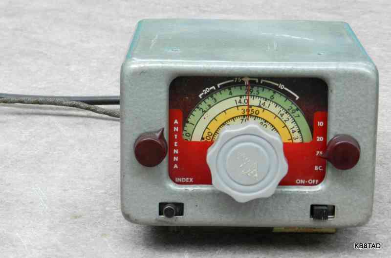
The Gonset Mobile Tri-Band is a converter designed for receiving the 75, 20, and 10 meter ham bands in mobile service. The car radio supplied the B+ and the remainder of a receiver system for dual conversion. Designed by Faust Gonsett, the Tri-Band follows the Gonset philosphy of a high quality but very compact design. It measures only 5 and 1/4 inches wide, 3 and 3/4 inches high, and 6 inches deep.
Some more history
In 1949, Gonset introduced a converter known as the "3-30". It covered the shortwave spectrum continuously from 3 to 30 Mhz in three bands. The Gonset Tri-Band was introduced in 1951 according the "VHF News".
Similar circuitry and form factor
All of these Gonset converters, the Tri-Band, the "3-30", and the early "Super 6" look much alike. The circuits are nearly identical for the three. The antenna jack and output cable use the Motorola jack and plug, as was common in car radios. The car radio was tuned to 1440 KHz, (1430 for the "Super 6") or very close. The Gonset was then switched from the straight-through position to one of three settings covering the shortwaves or selected ham bands.
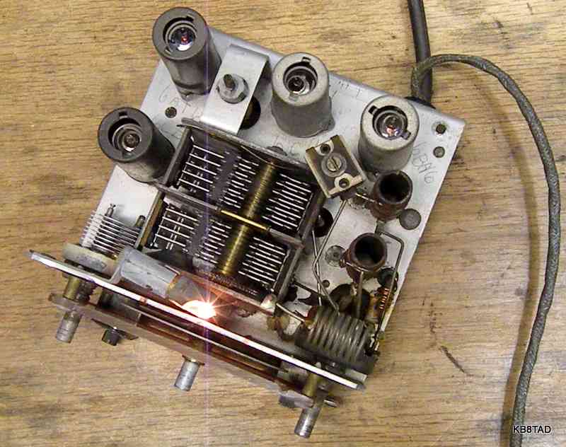
The Tri-Band uses only a portion of the travel of the tuning cap for a given ham band, allowing tuning on either side. This allows tuning to shortwave such as the 19 meter world band when in the 20 meter setting. Tubes in the Tri-bander are 6CB6, 6AT6 (or 6AV6), 6C4, and 6BH6.
Repair progress
As usual, I started with a thorough cleaning inside and out with white waterless hand cleaner. Deoxit was used on the switches, the variable cap rotor-to-ground feelers, and the tube sockets. I noticed that 10 meter coil L1 had burned open. This was made of a few turns of what appeared to be 22 gauge enameled wire. I surmised that somehow, battery voltage at fairly high current had been applied to the coil possibly by way of the antenna. I counted the turns and the spacing and rewound it. I also tested the band switch contacts to see if they had been damaged. Luckily no problem there. Testing the tubes found two that were very weak. I replaced those.
I determined which wire was for 6 volts and which was for B+ by simply connecting a 6 volt power supply between the ground wire shield and one of the other two wires. The one that took current and resulted in tubes and pilot light working was obviously the correct one for 6 volts.
I used a little Heathkit EF-1 power supply (pictured below) to provide the filament voltage and B+ power. Under load, the B+ measured at 135 volts, just about right for the converter.
I next used a frequency counter to see how well the oscillator would track and at what frequency. I was pleased to find that the counter showed a consistent tuning dial frequency plus 1430 or so KHz for each band. The little cap control on the lower left, labeled as "index", could adjust that to about 30 KHz higher or lower.
Trying out the converter
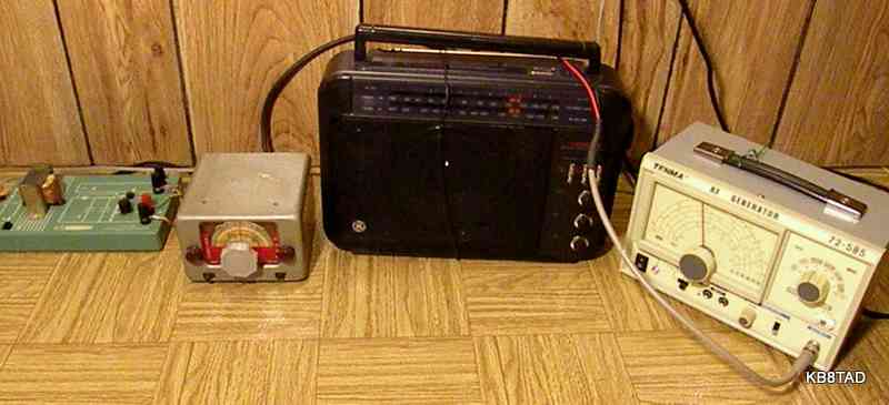
These converters were designed to be used with a shielded car radio. I did not have one handy so I tried it out with my GE SuperRadio using a single loop of wire wrapped around the set. The loop was connected to the converter's output cable. The loop wire injects a signal into the SuperRadio without any direct connection. I could also have used the SuperRadio's AM external antenna terminals.
I fed the converter's input antenna connection with a long piece of wire for antenna and later, my 80 meter dipole antenna. I listened to several shortwave stations on the 19 meter band (just below the 20 meter ham band). On 80 meters, I heard a number of muffled SSB transmissions. The little converter does AM only. It obviously preceded the wide implementation of SSB.
SuperRadio does shortwave and SSB
What would it take to make the little converter and the SuperRadio listen to SSB? I used a signal generator tuned to near 1430 KHz to inject some unmodulated RF. Its output is fed to a clip-lead draped near the top of the SuperRadio. The solid state signal generator pictured is fairly stable. By turning the generator's RF level to just the right amount of signal, SSB conversations were easy to tune with the converter and an occasional tweak of the antenna trimmer control and the lower left "index" control.
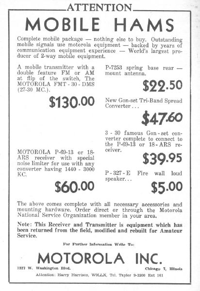
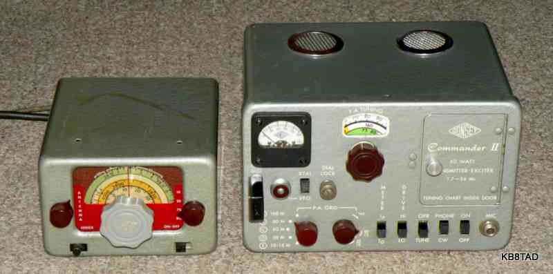
Converter meets the Commander
The
Gonset Commander was originally designed for mobile use with one of little Gonset converters such as the Tri-Band or the Super Six. Note the similarities in design. The Commander was happy to see one his brand-mates from the days of mobile AM ham radio.
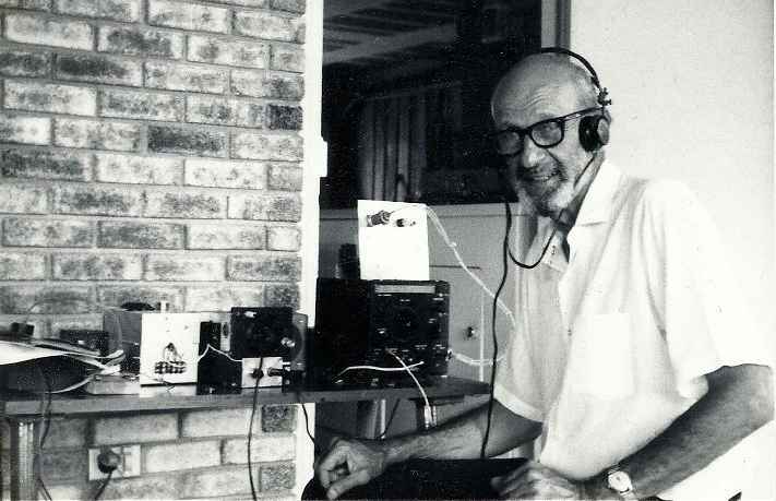
The Gonset Mobile Tri-Band converter came from the estate of Jim Mayer W5XF(sk). Jim wanted his fellow ham club members to enjoy some of his radio parts and pieces. I'm sure Jim would be pleased to know that his little Gonset Tri-Band is listening again. Yes, I would like to have had another conversation, what hams call an "eyeball QSO", with Jim regarding his Tri-Band, but the memories of all the eyeball QSOs we did enjoy will have to do for now.
Schematics
The schematic for the Tri-Band is on BAMA.
Click here for a link to BAMA and other manual sources.
The manual for the Super-Six can also be found on BAMA. Much of the information in the Super-Six manual also applies to the Tri-Band. Its addendum details the connections needed for conversion to 12 volt power for both the Super-Six and the Tri-Band. The Super-Six manual also mentions using a 45 volt battery for the B+ supply when using the converter with the "new" 12 volt-only car radios (radios that use 12 volt space-charge tubes and solid state audio output).
Date:8-20-11, update 9-2-12
Tube-era capacitor testers part 3. Open/ short testers were the previous items on the bench.