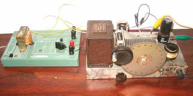
The potentiometer control on top of the chassis is a volume control connected between the two triodes of the 6SN7. Several hams have identified the variable capacitor as from an ARC-5 transmitter. The dial is a Bud 6929-A.
Home-Brew Regenerative Receiver
and experiments with low voltage operation.
I acquired this piece of "junque" some time ago because of the nice National S-101 audio inductor which is the type used by National in their famous SW-3. After identifying the chassis as a complete regenerative receiver, I decided to see what it was capable of doing. The tubes are a 6V6 used as the regenerative detector, and a 6SN7 used as a dual triode audio amplifier. In the absence of more exact data, I am assuming a build date in the early to mid 1950's. The little power supply shown with the regen is a Heathkit EF-1.
The potentiometer control on top of the chassis is a volume control connected between the two triodes of the 6SN7. Several hams have identified the variable capacitor as from an ARC-5 transmitter. The dial is a Bud 6929-A.
The chassis was marked "6V6" and "6SN7". It came with a 6SN7 but had a metal 6F6 plugged into the socket labeled 6V6. It appeared to have been experimented with after its original construction since several modern wires had been soldered in for B+ and filament connections.
I traced the circuit and checked to determine whether the audio inductor was intact and whether the caps were leaky. The phone jack on the front is insulated from the chassis and is in line with the B+ to the plate of the final 6SN7 triode. I will modify this to avoid B+ on the jack and a headset.
I checked the lone plug-in coil for resonance with my grid-dip meter. The coil has a small 250 pF mica cap inside, was built on a base from a discarded 4 pin vacuum tube, and is self-resonant at 4.25 MHz. When plugged-in, the coil and variable tuning cap were found to be resonant from 3.5 to 4.0 MHz, a perfect match for the 80 meter band. The original builder apparently knew his business.
Surprisingly good performance
I connected an output transformer and speaker to the phone jack and proceeded to power it up with the little Heathkit power supply. The set did not work well with the 6F6. The tube was extremely microphonic. Finding nothing out of the ordinary in a very simple regen circuit, I plugged in a 6V6 as originally intended. After a bit of warm up, the set came to life. Tweaking the 3 to 9 pF antenna trimmer (near yellow clip lead) brought the noise level up a bit from my 80 meter antenna. I was surprised at how well the little set worked. I listened to a number of SSB transmissions and some CW. The variable cap is a very stable worm-drive unit with no discernible back-lash that requires a full 50 turns to cruise the 80 meter band. The average of 10KHz per turn made tuning of SSB relatively easy. I was frankly amazed at what a stable and sensitive regen could do given a decent antenna.
"What frequency am I tuned to?"
We have an advantage that the hams of past generations could only dream about. We have the frequency counter. Just increase the regeneration a bit more and a frequency counter will sniff the exact frequency to which you are tuned because of the oscillating circuit. For my counter, I used a pickup loop of just one turn for 80 meters. For later AM broadcast experiments, I needed several turns for the loop. The pickup loop is placed near the regen's plug-in coil but not so close as to affect its tuning. Knowing the frequency of the regen is also useful when experimenting with temporary windings in the design of new plug-in coils.
Information needed. Use of beam tubes as regenerative detectors.
I have found information claiming that beam tubes make good regenerative detectors especially at low voltages, but have yet to find this exact circuit. If you have a schematic or article using a 6V6 as regenerative detector, please let me know.
In response to my request, Bob W2AMI showed pictures of hisvery nice regen known as the "Novice Special" from the June 1956 QST. It uses a pair of 6AQ5 tubes, one as regen detector and one as audio amp. The 6AQ5 is the 7 pin miniature equivalent of the 6V6. Bob also has a copy of the Novice Special schematic .
In searching for information on the net, I came across NA4G's very useful comments on homebrew regenerative receivers. NA4G, known as "Boatachor Bob", has lots of good "rules of thumb" for regens. In one of his observations, NA4G comments
For some good background on ham regens of the 1930's, read the January 2002 QST article by Al Klase on the "autodyne" with a nice review of the "rationalized autodyne". Lots of good information and a nice schematic. This link is to the PDF of the article. An "autodyne" radio is one using a regenerative detector. One of the comments on the "rationalized autodyne" is to keep the variable capacitance fairly large so that circuit and stray capacitances (such as hand movement) become a relatively small proportion of the total and of little effect. That design philosophy is apparent in this homebrew.
Voltage requirements for the homebrew regenerative
The filaments of the two tubes are wired in series with shielded cabling. The 6V6 draws a bit less filament current than the 6SN7. A resistor balances the two. The set actually worked a bit better with smoother regeneration control and reduced hum when the filament line is starved with about 7 to 10 volts or so on the pair compared with the full 12 volts AC. The little Heath supply measured about 7.1 VAC with the tube filaments in series which seemed to work quite well. With filaments starved a bit and feeding an output transformer and speaker, the set performed well on 80 meters with about 60 to 90 volts of B+ at a current draw of about 4 to 5 milliamps.
Hum reduction and new 50 cent B+ supply
Despite the shielding of the filament leads, a bit of hum was typical with this regen especially at the full 12 volts of filament when listening to 80 meter SSB or CW. I found that much of the residual hum could be eliminated by using batteries such as a 12 volt gel cell for the filament source. The full 12 volts also allowed the set to work well with a reduced B+ supply. I have a 30 volt DC 400 mA wall "wart" power cube that originally powered an ink jet printer and cost 50 cents at the local thrift shop. It has a no load voltage of 36. The regen works quite well with it. The wall wart just loafs at about the no-load voltage since the regen needs just a couple of milliamps. I tried stacking the 36 volts on top of the 12 volt gel cell being used for the filaments ("stacking" means the 36 volts are in series with the 12 volt from the gel cell ). Works great. My voltmeter confirmed 48 volts of B+. I will add a 500 ohm or so resistor in series with the wall wart B+ to avoid its dumping full voltage on the filaments in the event of a B+ short circuit. I'm thinking of using a DPDT power switch and that series resistor or other simple circuit to use the wall wart to trickle charge the gel cell when not operating the regen.
Making a coil for the AM broadcast band
I made a couple of temporary coils for the broadcast range but the tuning range was limited with this set due to the limited range on the variable capacitor. However, I found a tapped "loopstick" in the junque box. This is a tapped permeability-adjusted broadcast band coil designed for transistor radios. The inductance is variable from about 30 uH to about 240 uH, perfect for my needs. I wired the coil to a 4 pin tube base and adjusted it so that my favorite local broadcast stations were within the range of the regen's tuning capacitor. I added a knob so that the loopstick inductance could easily be changed to allow coverage of any point on the broadcast band as well as the 160 meter ham band.


Speaker volume at 12 volts on the AM broadcast and the short wave bands
I found that I could get usable speaker volume on local AM broadcast stations with only 10 to 12 volts of B+. That meant that a D.C. filament supply could also be used for the B+. At 12 volts, current draw for the B+ was only a third of a milliamp. Even lower B+ could be used with high impedance headphones. I found I could still operate the set on broadcast with only 4 volts on the B+ line using a 2000 ohm Cannon headset. In fact, the set would still pick up local AM stations with a B+ below about 3.5 volts, but at that point, the regen control would no longer bring the set to oscillation. AM, of course, is listened to below the oscillation point while SSB and CW are listened to with the set at some minimum oscillation point.
In an experimental set-up for a shortwave coil that would cover both the 49 and 31 meter international shortwave bands, I found that 12 volts was also a good choice for headphone and even for speaker level for a number of more powerful international shortwave stations.
I had read of the low-voltage capability of regen circuits in the book "Radio for the Millions" and had seen it mentioned by NA4G, but found it hard to believe until I experienced it myself.
Per requests received, I have drawn the schematic of the regen as found.
As noted, the 80 meter coil with its built-in 250 pF capacitor is self-resonant at 4.25 MHz. I did not remove the mica cap to determine its tolerance rating or a more accurate figure of its capacitance. Capacitance of the wire would add to that figure.
The coil itself consists of 11 - 1/4 total turns with the tap at 1 - 1/2 turns from the grounded end on a 1 - 3/8 inch diameter form. The top 9 - 3/4 turns are 5/8 inch wide on the form. The form has saw cuts on the bottom to provide an air gap between the pins. I believe that was a common practice of the era to increase the "Q" of the coil somewhat. As shown by the dotted lines, shielded cabling was used for wiring to the RF choke, the audio inductor connections, and the series-connecting filament lead. The main variable was measured at 50 pF to 185 pF on a Sencore Z-meter. Note that this includes circuit capacitances, but the 80 meter coil was removed to make the measurement.
Calculators for designing new coils
The following links are for simple calculators which will help in winding new coils for regenerative sets such as this one.
Here are two links for calculating the number of turns for a given coil size to achieve a selected inductance:
Approximate Air Coil Inductance Calculator and
Single Layer Air Coil Inductance Calculator
Here's a link for calculating the necessary capacitance and inductance for resonance at a particular frequency. L/C Resonance Calculator
Two Heathkit Signal Generators as "broadcasters" were the previous items on the bench.