
Hallicrafters version of a panadaptor display
In 1946, Hallicrafters introduced the Skyrider Panoramic model SP-44. It is essentially a Hallicrafters logo version of the Panoramic Radio model PCA-2 T-200 . Since the Panoramic Radio company used a Hallicrafters S20R receiver to show off their PCA-2, I connected the SP-44 to the S20R.
The Skyrider Panoramic is a spectrum display which portrays visually the signals in a selected part of the radio spectrum. It is connected to a receiver's converter at the input of the first IF amplifier stage. Connecting at a further point reduces the spectrum width. The SP-44 is designed for a receiver having an IF between 450 and 470 KHz. The signal being listened to is at the center of the display. Signals nearby in frequency are also displayed as pips of varying shape to the left and right of center. Pip shapes vary with the type of transmission. For example, the pips of SSB signals appear to come up from the base line and then drop back down again as words are spoken. AM signals will increase in height with modulation and their sidebands are often visible on stronger signals. CW (code) signals appear and disappear as very narrow pips as the carrier is turned on and off when keyed for code.
This SP-44 was sent to me by Herb J. in Texas for the cost of shipping and a donation to his church. Thanks Herb.
Troubleshooting notes
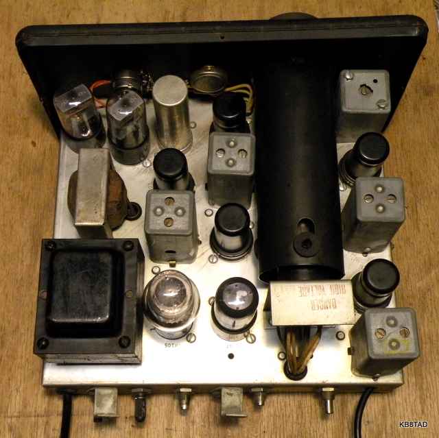
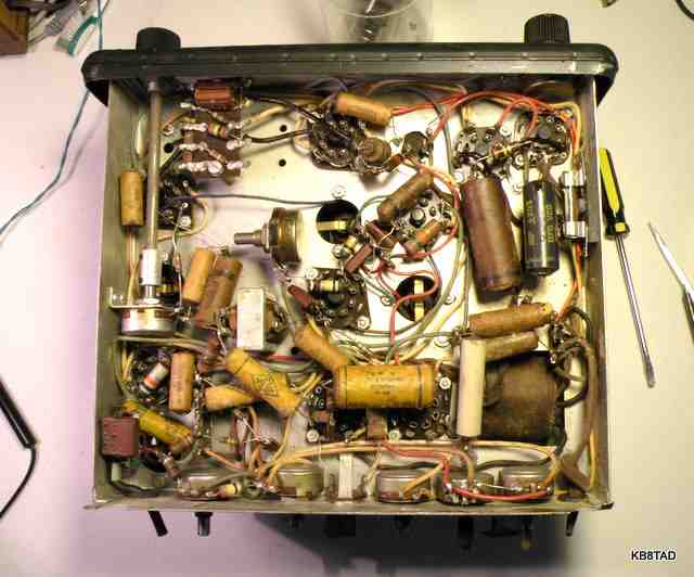
The SP-44 had both the power cord and the input coax cable cut off. I replaced what was left of the two-wire power cord with a new shielded three wire power cord. I also rewired the power leads to modern standards with the "hot" lead going directly to the fuse and then to the power switch. The neutral lead is fed directly to the power transformer.

I had no means of testing the 2AP1A cathode ray tube prior to starting repairs. With all caps except for a few micas replaced, it was time to see if the CRT had survived the years and the Post Office shipping. To my relief, a green trace appeared after a slow power-up.
Sparks and snaps
The trace could be adjusted as needed for focus and intensity. I had the chassis on its side so that I could monitor both the B+ voltage and the very high negative voltage. Suddenly there was a spark with a loud "snap". Luckily I saw the spark location. I quickly shut the unit off and drained the caps of any voltage. The spark had been visible at the back of the intensity control which carries a high negative voltage. I noticed that the solder on the control's center lug appeared a bit thick resulting in a solder blob that was very close to the metal body of the control. The high voltage had simply arced over a very narrow gap. It was likely a factory defect. I heated the connections, removed the excess solder, cleaned up the wiring, and inspected the other controls carrying high voltage. There were no further snaps and sparks.
The coax input lead had been cut off. The length of the lead on my PCA-2 T-200 was about 30 inches. I made a near match out of light flexible coax and added a 50K ohm resistor at the very end as called for in the schematic.
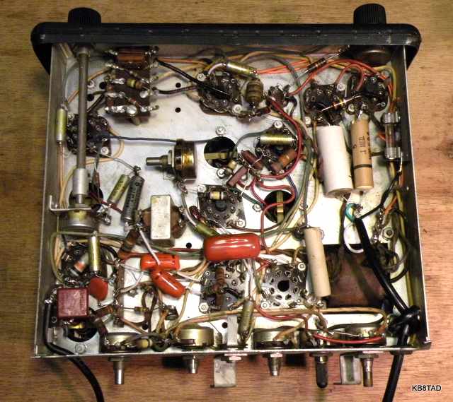
The trace on the CRT was visible with a signal generator input of 455 KHz and could be adjusted by the Sensitivity control. However, there was no response from the Scanning Width or Centering controls. Further troubleshooting led to an open RF choke. While I had some possible replacement chokes, I tried to repair the original. I used a hair dryer to melt the wax coating on the ends. The air flow from the hair dryer caused the hot wax to flow away from the ends allowing ready access to the thin choke wire which had broken at the solder joints on the choke itself. After a couple of attempts, the little choke was successfully repaired. After re-installing the choke, the SP-44 was working as it should.
Connecting to a receiver
The original design for connecting to the converter tube in the receiver consisted of either a permanent connection or temporary connection with a small loop that slipped over the converter tube plate pin. Since the tube plate pin carries receiver B+, the temporary connection struck me as a bit of Rube Goldberg just waiting for a short circuit. I decided that a better solution for the receiver side was simply adding an adapter made from a tube base and tube socket with the plate connection fed by a bit of wire and an insulated connector to the SP-44 coax. If I were to do it again, I would place the 50K ohm isolation resistor inside that homebrew adapter as well so that even a short circuit to ground on the connector or coax would be current-limited to only about 5 or 6 milliamps and therefore not damage anything.

Using the SP-44
As a spectrum display, the SP-44 is a nice accessory to a vintage tube receiver allowing the user to see signals near the one being heard. It is fun to see each of those signals move to the center of the display as they are tuned in via the companion receiver. The signals can be identified as to type of tranmission and signal strength even before they are tuned in. The fading and rapid changes in signal strength can easily be seen. The picture above was taken on my camera's "sports" setting so as to capture an image quickly without the blur that would be caused by the rapid fading.
BAMA has an excellent SP-44 manual in PDF format scanned at 720 dots per inch. See the home page for a link.
The Hallicrafters SP-44 was pictured with the SX-42 on the cover of the March 1947 Radio News magazine.

The Conar Twins 400 transmitter and 500 receiver
were the previous items on the bench.