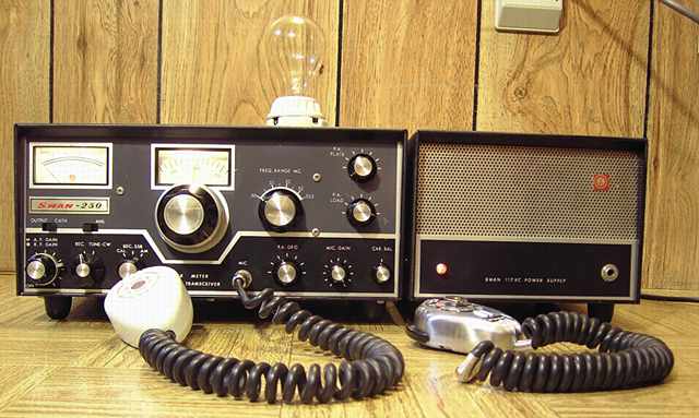
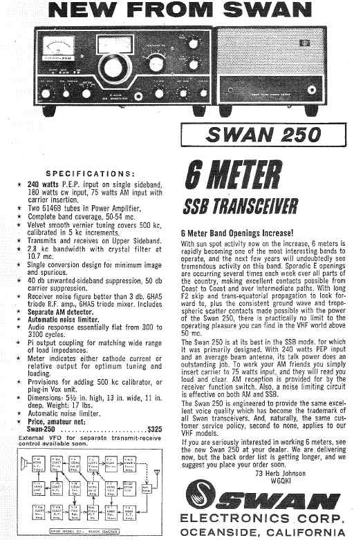
The Swan 250 transceiver for the 6 Meter ham band was introduced in 1966 at a cost of $325. The matching 117XC power supply was an option at $95. RF output is from two 6146B tubes. The set is rated at 240 watts PEP, 180 watts CW, and 75 watts AM.
First 6 meter SSB encounter
This Swan 250 with matching power supply and mike, all in very nice cosmetic condition, were sent to me as a good home. Many thanks to Bruce N4JAD. It is the first 6 meter SSB transceiver I had ever encountered. Lots of new learning needed to take place. One of the nice things about tube equipment is that it is relatively forgiving of simple measurement mistakes. However, one must be very careful with the high voltages encountered.
Checking out the power supply
The 117XC on the right matches the Swan 250 cosmetically. I removed the smaller box that is the actual supply from the 117XC cabinet. Some of the wires inside as well as in the umbilical had the insulation partly melted. Those wires went to the 117 volt on-off switch located in the companion transceiver. Inspecting the power supply case revealed that one of the partly-melted wires had also touched one of the high voltage capacitors in the upper stack. Marks on the aluminum cover as well as a burnt piece of wire indicated that significant arcing had taken place. I replaced the partly melted wires with somewhat heavier hookup wire of the same color code and rerouted the wires away from the high voltage points. I also inspected and re-did some of the connections in the umbilical. Heat shrink tubing was added as needed to the wear points. The 117XC uses a unique Jones connector for its AC power cord. It contains a fuse holder mounted in the connector. After determining which connection would be chassis ground, I changed the power cord to a 3-wire grounded version, making sure that the line connection (the hot side of the AC) went to the fuse and then to the power switch. The neutral goes directly to the transformer.
After carefully inspecting the wiring and doing some tests on the diodes and electrolytics, I slowly powered the 117XC with my isolated variac while checking at various voltage levels to make sure the series electrolytics were evenly dividing the voltage. The electrolytics reformed properly and divided the voltage as intended. Like most transmitters and transceivers, the power supply has two high voltages, one for receiving and the low-level transmitting stages, 275 volts in this case, and a second much higher voltage, 800 under load and over 925 at no load.
Compared to some other power supplies with independent high voltages such as the Heathkit HP-23 series, the Swan stacks the two to obtain the highest voltage. About 525 volts (under load) is added to the 275 to obtain the 800 volts. That allowed Swan to only use three levels of 350 volt electrolytics, one for the 275 volts and two in series for the 525.
A further problem developed with the power supply. The 12 volt filament line opened intermittently. I traced the problem to a bad solder joint at the input Jones connector.
Swan mike, bad element
The nice brushed-chrome Swan mike (on the right, not plugged in) needed a plug attached and some internal repair. The crystal element was dead. I opened the element to find that the ground side connector was disconnected. I managed to repair it with a new bolt and a flat washer to hold the connector strip to the case. While the mike worked after repairs, the element had unfortunately deteriorated. Its output level was too low to use. I will look for a substitute element. In the meantime, I used a known-good Turner 350.
Powering up the Swan, weak receive
With the power supply in good order and with the Turner mike connected, I powered the transceiver. The Receive function worked but was extremely weak. The transmitter side did nothing. Sniffing the transistor VFO with a frequency counter showed that it could track properly. The tube VFO tripler was also functioning. Testing all tubes revealed a weak 12BA6 IF amp tube and one very weak 6HA5 RF amp tube. I replaced both. That made a noticeable difference. I tweaked the input coils to the 6HA5 as noted in the manual. That helped somewhat more. However, receive still seemed rather weak. At full RF gain it was also a bit unstable.
Repairing an open IF peaking coil
I adjusted the output IF coil for maximum noise per the manual instructions. It peaked easily. However, the input IF coil which is also used as part of the transmit function was stiff and somewhat difficult to turn. In checking the coil continuity, I found it open. I unsoldered and removed the IF coil and its shield housing. The ferrite adjustment slug had been cracked and was jammed in the coil sleeve. The sleeve itself had been twisted loose from the base. Both of the coil wires had been pulled off the solder lugs. I resoldered the broken wires and used cyanoacrylate glue to join the sleeve and the base again. I also measured the ball park value of the inductance of the coil in case a successful repair was not possible. That would enable a replacement. After the glue set, I used a drill bit clamped in vise grip pliers to manually but gently "drill" the ferrite slug, starting with a small bit and then a larger one. The ferrite came out in pieces. I located a donor coil for a replacement slug. Using a grid dip meter, I confirmed that with the replacement ferrite slug, the coil and its little fixed capacitor could be resonated at about 10 to 11 MHz. I remounted the coil assembly in the circuit, tweaked the alignment, and noticed a much improved receive. I also neutralized the input circuit of the RF amp tube I had replaced. That solved the instability at maximum RF gain caused by regeneration at some settings of the PA grid control. However, the transmitter still would not function.
Mixer and driver output coils, loss of inductance
I used the grid dip meter and my frequency counter to properly set the VFO tripler coil. The mixer and driver output coils were also checked, but neither of those coils could be adjusted down to 50 MHz resonance. The coils use a piston-shaped ferrite with a metal adjustment screw. Adding 5 pF succeeded in just bringing the coils down to 50 MHz. I finally added a 10 pF dipped mica across each coil to get the proper range on the coils with a bit of margin. One characteristic of ferrite is declining permeability with age. I suspect that the ferrite in those coils, which had aged some 40 years and were also subject to some RF heating, had lost permeability resulting in coils which were no longer capable of achieving their full inductance.
Carrier crystal surprise
According to the manual, the Swan 250 was designed around a 10.698 carrier oscillator. Imagine my surprise when the frequency counter read the carrier crystal output at 10.898 MHz! Thinking someone had replaced the crystal with the wrong one, I quickly checked the manual for both the 250 and the 250C. Apparently, Swan used a 10.898 crystal in the 250C. To my relief, the crystal filter in this set read "Model no. 10.9-2.8". Apparently Swan had substituted the carrier crystal and filter planned for the 250C in the later manufacture of the 250.
Up scope
At this point, my ignorance of the circuit was starting to show. While the idling current of the tested-like-new 6146B pair was easily adjusted to 40 mA as specified in the manual, nothing further was happening. Carrier balance showed just a slight dip in current. I suspected that the mixer and driver were not providing sufficient RF voltage. Time for the oscilloscope. I don't use a scope often enough, so I used a signal generator to preset the scope to expected frequencies so I would recognize what was on screen. With the Swan tuned to 50 MHz, I rested the 10X scope probe in the center of the mixer coil for capacitive pickup. The mixer adds the 10.9 MHz to the 39.1 from the VFO using the resonant 50 MHz circuit at its output. On transmit, the scope showed a proper frequency but insufficient RF voltage. I had already pre-set all of the coils in the Swan. With the scope probe in the VFO tripler coil (at 39.1 MHz), I maxed its voltage output a bit with the trimmer cap. I adjusted the coil a bit and confirmed that it was already peaked. Returning the scope probe to the mixer coil, I adjusted its little cap for maximum as well. Leaving the probe at that position, I then adjusted the carrier crystal trimmer. That adjustment kicked up the voltage significantly. At this point, I was rewarded with a much increased cathode current when I keyed the transmitter. I also noted that just a little bit of adjustment was critical in each of the settings. Having the scope was very helpful.
It works again!
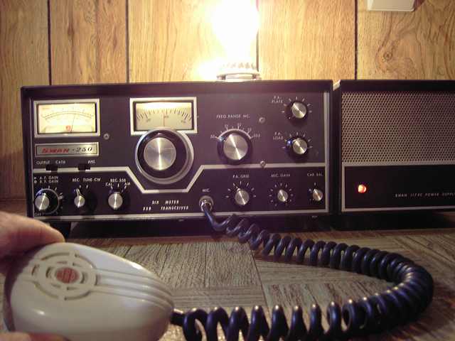
I now could tune the transmitter to full output. The carrier balance control could null properly. With it centered on the carrier null, my 60 watt light bulb dummy load could flash to full brightness in time with speaking into the mike. I still have much to learn about tube SSB tranceivers, but this one is working again. Let me know what shortcuts and tricks you have learned in your repairs and restorations.
On-the-air test
I fired this Swan up for the local 6 meter AM net, probably its first on-air use in quite some time. Receiver was excellent. I had the carrier injection at the suggested 80 to 90 mA setting per the manual but needed a bit more for decent AM. I also suspect that the Turner 350 mike may not the best match for the set. Will try to repair the Swan mike. As an alternative, I suspect that an older high-impedance D-104 would probably be a good choice.
The Fisher TA600 receiver was the previous item on the bench.