
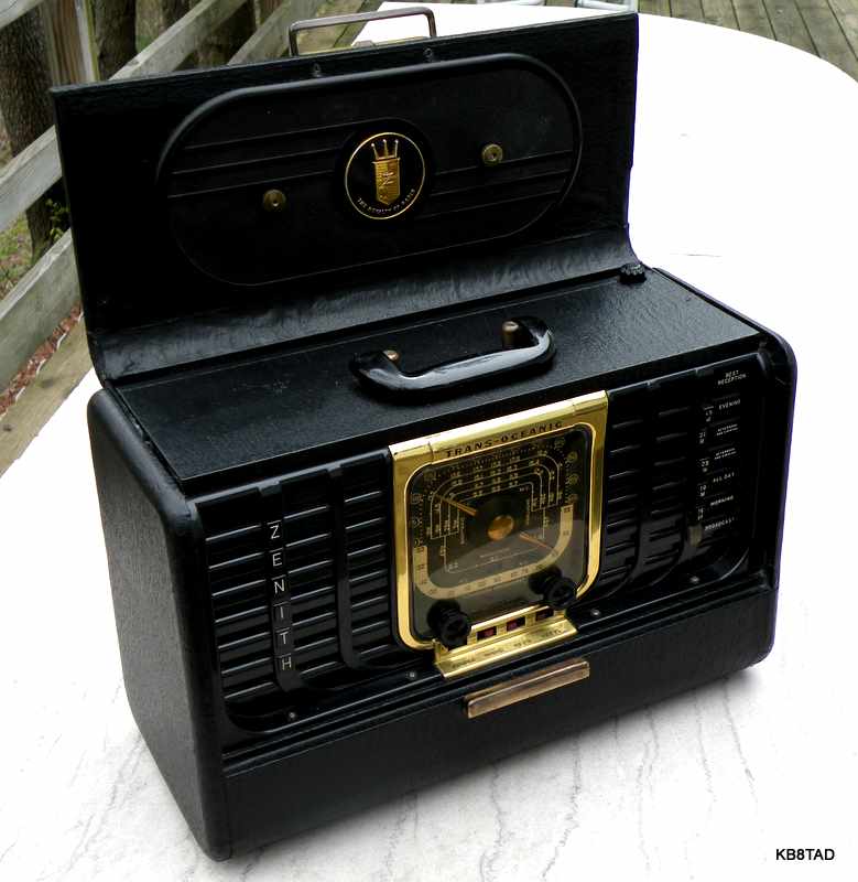
Zenith Transoceanic G-500 Receiver
The Zenith Transoceanic model G-500 is often called the "transition" model. Introduced late in 1949, it was replaced by the H-500 in early 1951. With a model run of less than 2 years, there were fewer G-500 sets made and fewer in existence today. It also sports the unique "Royalty of Radio" emblem. As a result, the G-500 tends to be one of the more sought-after models.
Externally, the G-500 looks nearly identical to the prior model 8G005. Compared to the 8G005, the G-500 has the emblem on the Wavemagnet and brass mounting nuts. It also has a more substantial folding handle like all later models, but eliminates the handy front drop-down compartment. From a distance, the only differences are the emblem and mounting nuts on the Wavemagnet.

Inside, the G-500 is a very different radio. It no longer uses the larger loctal tubes or the tube rectifier of the 8G005. In fact, the chassis looks like a prototype for the later H-500. The tubes are all 7-pin miniature types that became the standard for all later tube Transoceanics. Tubes are two 1U4, one as RF amp and the other as IF amp, the expensive 1L6 converter, 1S5 as detector and audio preamp and 3V4 as audio output.
All of the Zenith Transoceanics are favorites as sensitive portables for broadcast band with the movable "Wavemagnet" antenna and short wave listening using just the built-in telescoping whip antenna, assuming the radio is working well. The bands are all push-button selected with the shortwave selections covering the international "world-band" shortwave segments, allowing ease of tuning for those not skilled in using communication receivers. No bandspread is needed.
Zenith advertisements for the G-500 and other Zenith portables can be found in popular magazines of 1950 and late 1949. Ads were placed in the Saturday Evening Post, Holiday, Colliers, and others.


Opportunity comes along
I bought a G-500 some years ago in awful condition. The cabinet was in poor cosmetic shape and the set had been home to a mouse which, besides building a nest, had left his calling card as evidenced by corrosion on the speaker metal and chassis parts. However, the set was complete except for the Wavemagnet antenna, knobs and one of the push buttons and, of course, the price was right.
A few months ago, another G-500 was auctioned that had been stripped of parts such as tubes, rod antenna, cabinet latches, knobs and push buttons. I purchased it at a reasonable price as well. The chassis and the cabinet were in good cosmetic condition, the Wavemagnet was present, and I knew I had most of the missing parts. (Sharp eyed Transoceanic fans will notice that the knobs and the Broadcast push button on the G-500 are not quite correct for the model.)
Schematics
The schematic, alignment information and the owner's manual for the G-500 and other transoceanics can be downloaded from the Nostalgiaair website .
Repairs
Most tube Transoceanics suffer from:
This G-500 suffered from all of these problems.
I pulled the chassis and used contact cleaner on the switches, tube pins and sockets. The power cord had been cut off. I replaced it with a similar non-polarized cord. I monitored the filament voltage (from B- at the electrolytic shell connections to pin 7 of the 3V4) while powering the set slowly from my isolated variac. The filament voltage barely made it to 6 volts at full line voltage. Conclusion: worn out selenium rectifier. I disconnected the selenium, added a terminal strip on its mounting bolt, and used a pair of series connected 1N4007 diodes for replacement.
I then adjusted the input voltage to see at what point the set would play well. It required over 8.4 volts on the filament chain just to play on the broadcast band. At 9 volts on the filament chain the set was barely able to function on the lowest shortwave band (49 meter). Tentative conclusion; very weak 1L6 . Tentative because I had not yet replaced capacitors. However, subbing a known good 1L6 confirmed the conclusion. A Transoceanic that can play well on the upper short waves with normal filament voltages from 7 to about 8.4 has a good 1L6. I judge a 1L6 by the filament voltage required for that tube to function at the highest shortwave band (16 meters). Nine volts is the absolute maximum that the filament chain should be subjected to at high line voltage. I use my frequency counter to determine the point where the 1L6 fails to function as oscillator.
I replaced all of the color-striped Sprague "Black Beauty" capacitors except the three on the low impedance tone control switches. Black Beauty caps are typically leaky and therefore any high impedance circuit can be affected. However, when bridged by low resistances or subject to only low impedance and low voltage circuitry as in the Transoceanic tone-switch circuit, there is seldom a reason to replace them.


Wavemagnet Connections
I next checked for continuity at the lid-hinge and wire connections to the Wavemagnet. One side was open circuit. It had continuity from the chassis connector to the hinge but none to the Wavemagnet stud. I gently pulled back the cover material to gain access to the braided wire that connects the hinge to the Wavemagnet mounting stud. I found that the braid had never been soldered onto the hinge. The connection from the braid to the mounting stud was also open with a bit of corrosion at the base. I scraped and cleaned both connections thoroughly and soldered the braid onto the hinge. For the stud side, I cleaned and tightened the physical connection but also wrapped a couple of turns of tinned wire around the base of the stud and soldered the wire directly to the braid. I wanted to be doubly sure of good connections before gluing the cover material back onto the lid.
Substitution for 1L6
While I could borrow a known good 1L6 from one of my other Transoceanics or clones, a new one is very expensive. I decided to try one of the known substitutions, a 1R5 with pin 5 removed. The 1R5 is said to perform adequately to 10 MHz. I was pleased that with relatively low voltage on the filament chain, about 7.8 to 8 volts at full line voltage, the set performed well to over 12 MHz.

Another possible substitution would be to use a 1LA6 with a socket adapter. The 1LA6 is the large loctal equivalent to the 1L6 and is used in the 8G005 and the prewar Transoceanic. The chassis tube socket hole for the 1L6 in the G-500 is larger than the socket holes for the other tubes in the set (obvious in picture above) leading to speculation that the larger chassis opening may originally have been intended for the use of a 1LA6. Of course, it may also have been to limit the effect of capacity on the oscillator circuit. For lack of a seven pin plug, I have not yet tried the 1LA6 substitution.
Alignment
I found that alignment (with a borrowed 1L6 in place) on the 16 meter band was not possible without circuit modification. I have run into that with other Transoceanics. I suspect that aging coils and components may be a factor. Let me know if you have run into this problem and what you did to resolve it.
For now, I decided to align the G500 on the broadcast and 25, 31, and 49 meter bands with the 1R5 in place. Re-alignment in a Transoceanic is not that difficult if I later decide to replace the 1R5 with a proper 1L6.
Performance
Despite using the 1R5, the G500 proved to be a very good performer on broadcast and the lower shortwave bands. Like the other Transoceanics and clones, it is a fun set to use.
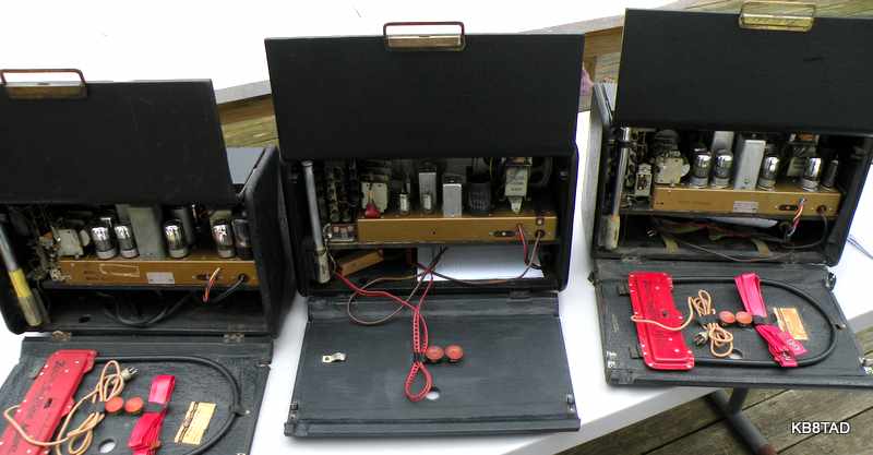
Transoceanic party
The H-500 Transoceanics (back row right) were so delighted to see their prototype brother, they decided to throw a welcoming party for the G-500. They even invited some the clones. Here is the group picture with all of them waving their rod antennas. That's the R-600 and T-600 (back row left), the 8G005YT and 8G005TZ1Y
(center row flanking the G-500). Front row left to right, Sonora GTU number 604, RCA Strato-World , Hallicrafters TW-2000, and Hallicrafters TW-1000 .

Update
Ellis E. wrote regarding the 16 meter alignment problem.
He notes, "on page 140 of Schiffer's Trans-Oceanic Royalty of Radios book, he gives a 'hint' regarding 16 meter band alignment. Move the wire from the 16-meter band oscillator coil to the grid of the 1L6 away from all metal chassis parts. Hope this helps."
That is an excellent hint, Ellis. Anything that will reduce the capacitance in that part of the circuit should help. I have thought of simply pulling a turn or two off the 16 meter coil to increase the upper range, but I will try this simple idea first.
date: 4-9-11, update 4-11-11
A Hallicrafters SX-130 receiver was the previous item on the bench.